Student Presentations:
Assignment 6.3:
Movie Diagram
The class will divide up into teams. Each team will get one of the following movies and together create a narrative diagram of it.
- Inception
- The Hangover
- Pulp Fiction
- City of God
- Die Hard
- The Royal Tenenbaums
- The Big Lebowski
- Dunkirk
Divide up into teams. Watch the movie then decide what information to depict it as a diagram. How can each team member best contribute?
Upload a color PDF to Miro for Week 8. Size should be at least 2160×1920 pixels.
Assignment 6.4:
Illustrator Tracing
Use Illustrator to trace a diagram from this pinterest page
Upload a color PDF to Miro for Week 8. Minimum 1920×1080 pixels.
01 Operative Diagrams

Click here for previous students’ examples
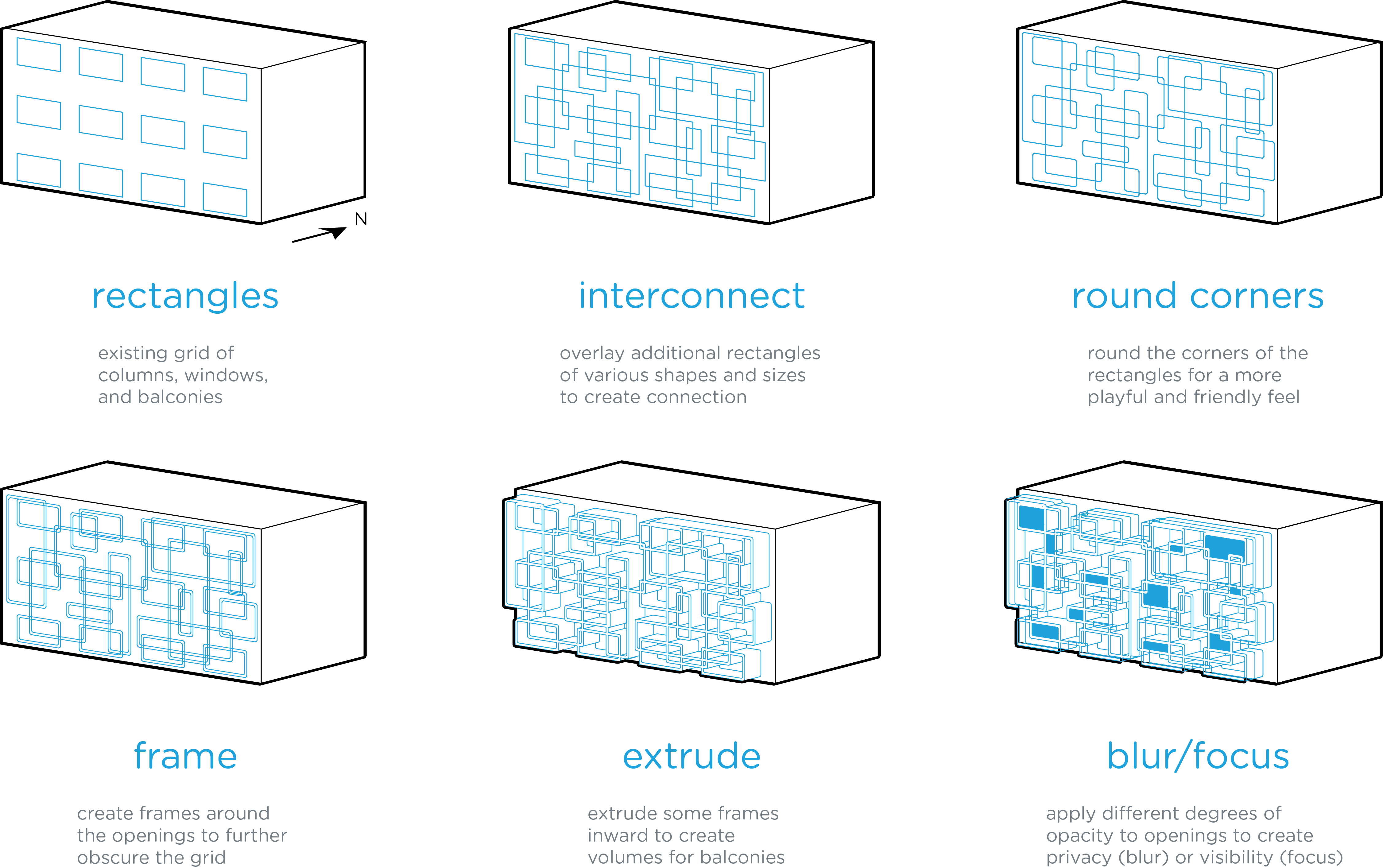
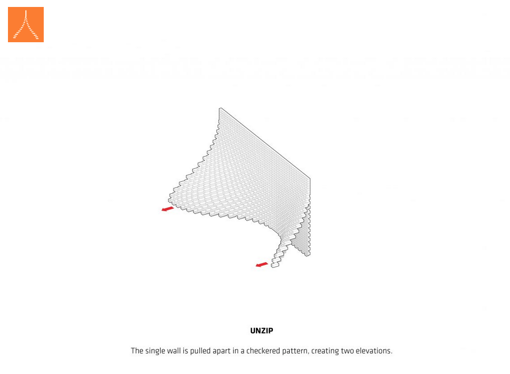
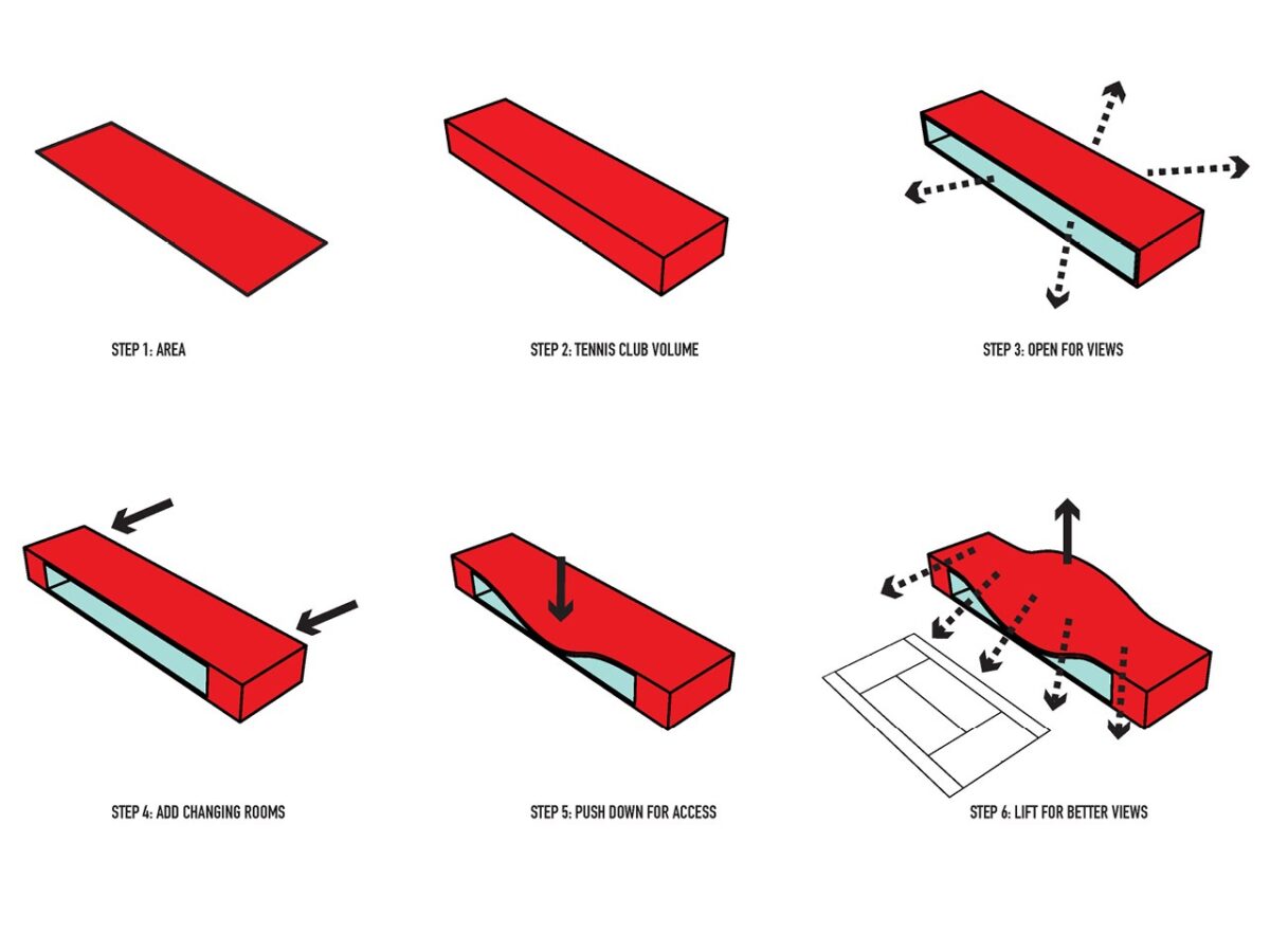
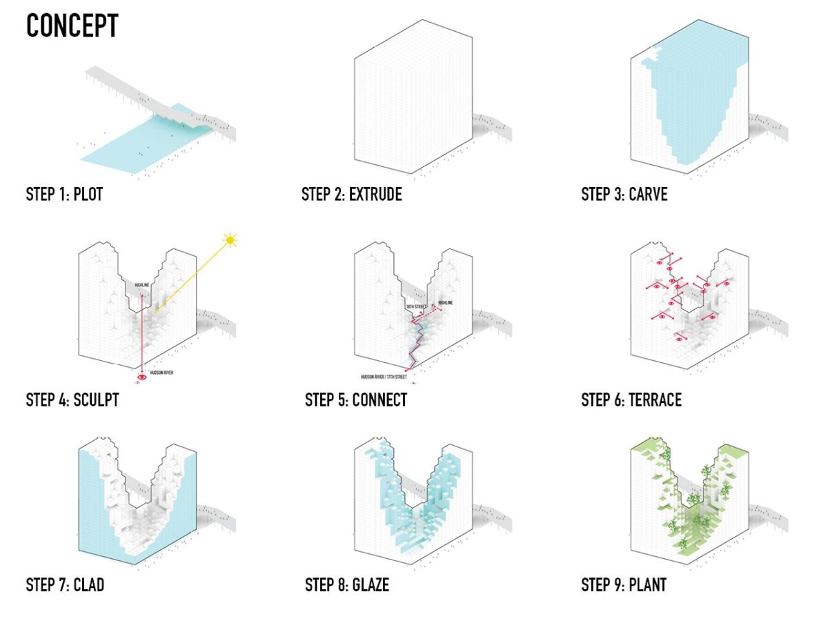
The Operative Diagram describes the formal manipulations used to transform a simple shape into a complex one.
They reveal and illustrate the sequence of individual steps in the transformation process.
The reasons behind each operation are explained and the movements displayed. There are many reasons that an operation could be performed. Some general examples:
- To create spaces or openings for circulation
- To respond to environmental phenomena such as sunlight, wind, or sound
- To introduce variation and dynamism in an otherwise static arrangement
- As a response to views, both in and out
- As a means of dealing with any number of program or site concerns
Use your 3D Analytical Site Diagram graphics to help explain and justify your Operative Design design decisions.
Operative Diagrams should be able to explain to non-designers:
- DERIVATION of form and space
- CONCEPTS being translated into form and space
- REASONS for conducting each operation/manipulation
And many more examples in these Program Diagram books (out of print, hard to find, and expensive to buy – try a library):
Architectural and Program Diagrams
Architectural and Program Diagrams 2
Building a diagram as an afterthought
Facade Operative Diagram Tutorial
by Yo Sensei
Yo’s tutorial goes through modeling for the first half. The important thing to know is how he models each step in the facade development process and organizes the layers. Summary:
-
- In Rhino, save a Named View that is a 3D parallel projection.
- Create geometry that shows the starting primitive form. Save on its own layer.
- Copy the geometry to a new layer and alter it to create the first step in the operative sequence.
- Copy the new geometry to a new layer and alter it to demonstrate the next step. Repeat for as many steps as you need.
- Skip to 28:26 to see how the Make2D objects are created in sequence, arranged on layers, and exported to Illustrator.
- The Illustrator portion starts at 34:19.
Download scaled people for Rhino here
Additional Graphic Treatments
– Shape Builder tool settings for color
– Preview/Outline mode toggle for precise drawing
– Select Same Fill/Stroke
– Swap Fill/Stroke
03 Lab Time / Desk Crits
Assignment 8.1
Create an Operative Diagram Series for your ENV3 facade design.
Format it as a sequence of individual diagrams on one or more 1920×1080 layouts. Each individual diagram should focus on a particular operation and illustrate very simply the decision made in that step.


